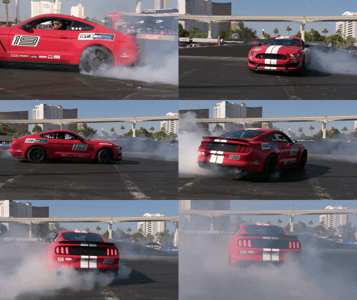
The purpose of this lab is know our car a little better and to set up the virtual robot simulator.
The very first step of charactering our car would be to take some simple measurements of the car and the battery, such as dimensions, mass, and how long it takes to charge as well as drain the battery. Using a tape measure, a scale, and a clock, the following measurements were taken.
| Length | Width | Height | Wheel Radius | Weight (Car) | Weight (Battery) | Est. Max Charge Time | Est. Max Usage Time |
|---|---|---|---|---|---|---|---|
| 15.7cm | 13.8cm | 12.1cm | 3.73cm | 454g | 50g | 240 min | 25 min |
Nothing about the car is surprising, except the weight of the car, which is exactly 1 pound. The battery measurments are a little tricky. The first time I charged it, the LED stopped blinking in about 2 hours, so the battery pack probably still had leftover charge. I then ran a series of tests with the fully-charged battery. After 20 minutes, the car was a little slower compared to earlier, but it was still very much functional. With the (I assumed) almost fully-depleted battery, the charging time went up to about 3.5 hours, which is still lower than what the instruction manual suggests. Interestingly, the instruction manual has instructions in two languages, each sugessting a different charging time.
There are a few interesting metrics that we can measure, such as maximum speed, maximum acceleration, and braking distance. We can also explore more practical scenarios such as stopping at a wall.
First, the maximum speed that our car goes. The way I measure this is by setting up a starting line and a finish line. A stopwatch is placed right next to the starting line with a camera hovering on top. Then, the camera is able to capture the exact moment the car passes the starting line as well as the sound of the car hitting the cardboard box.
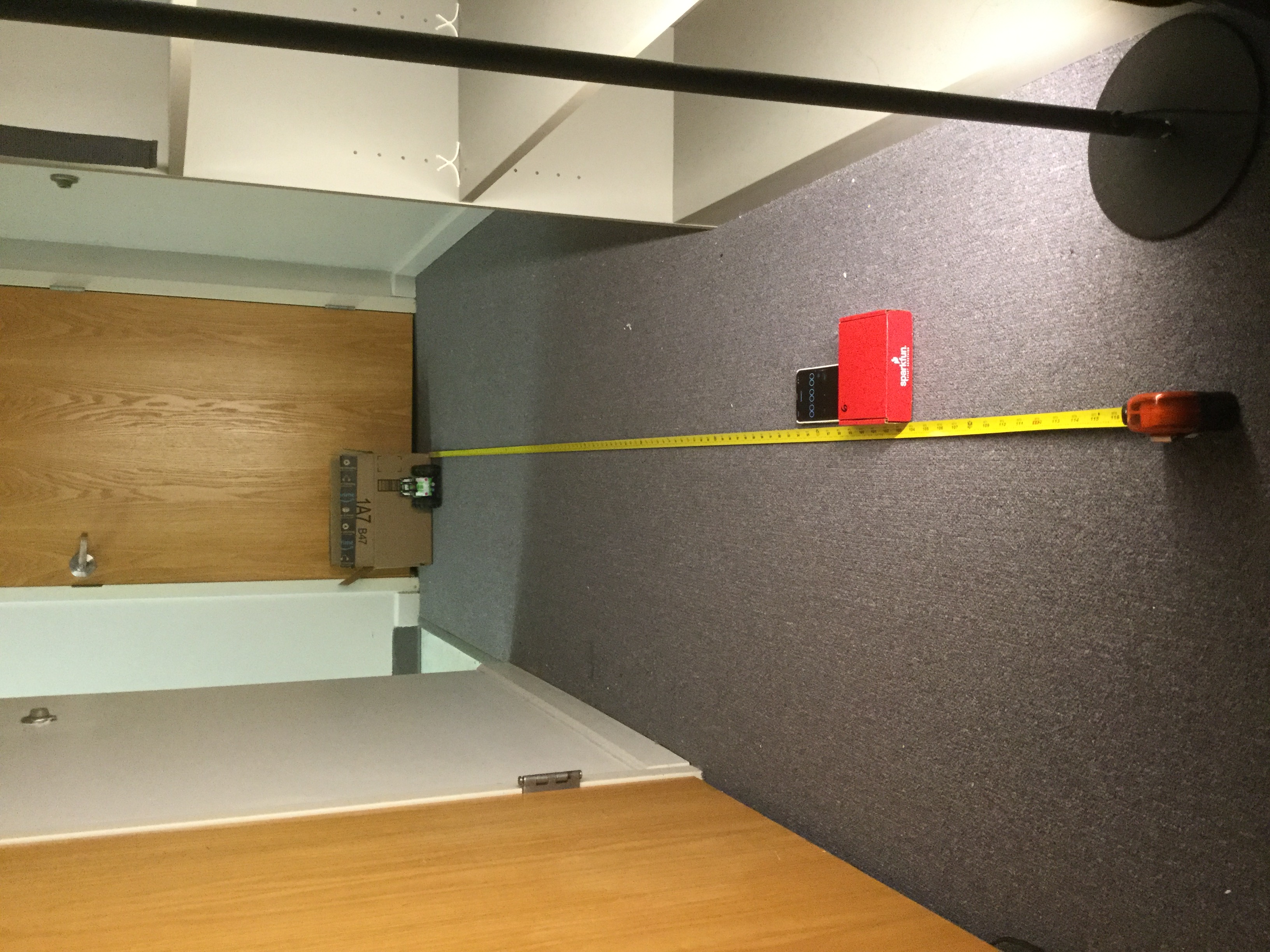
With the distance and the times, we can now calculate the speed using the following equation.
\[ v_{max}=\frac{d}{t_{end}-t_{begin}}\]
To reduce error, I conducted two trials and gathered the following data. Unfortunately, the car does not want to follow a starightline and hit the door behind the cardboard box both times while travelling in a curve. The distance traveled is now an educated estimation.
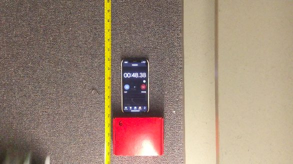
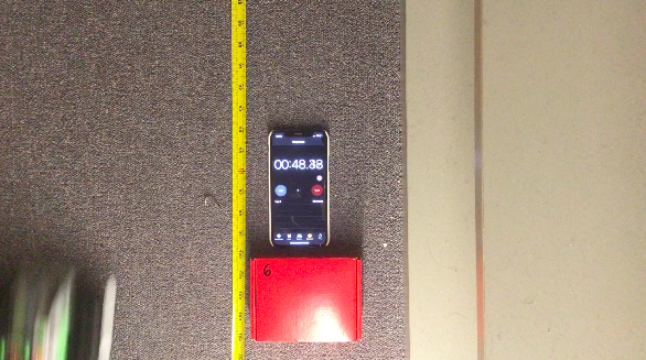
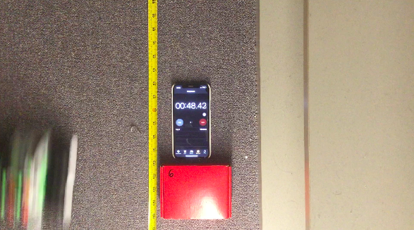

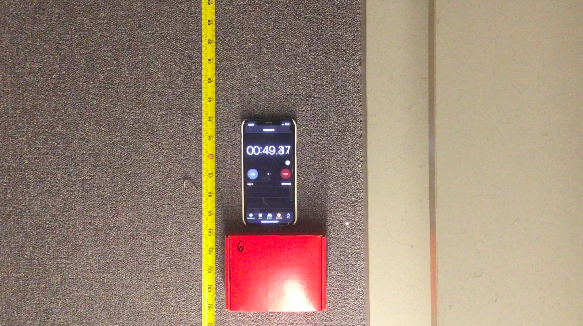
The velocity can therefore be calculated as follows:
\[ v_{max}=\frac{d_{est}}{t_1-t_2}=\frac{279.4cm}{49.39\,s-48.40\,s}=282.22\,cm/s \]
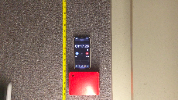
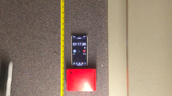

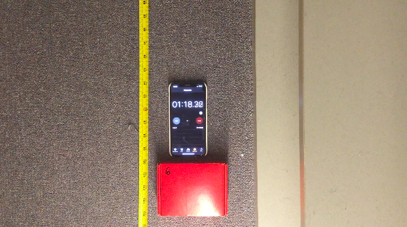
The velocity again can be calculated:
\[ v_{max}=\frac{d_{est}}{t_1-t_2}=\frac{279.4cm}{18.32\,s-17.29\,s}=271.26\,cm/s \]
Therefore, the maximum speed is approximately \( 2.75\,m/s \) on my carpet.
The maximum acceleration and braking distance are a lot harder to measure. To best measure acceleration, the IMU used by lab 6 is probably ideal. The braking distance is impossible to measure because of the center of gravity of the car. When traveling at max speed, the car rolls extremely easily if deceleration is applied.
In the previous section, my carpet was briefly mentioned. It plays a much more important role in this part.
As we can see, spinning is much easier on my kitchen floor, likely due to the extra friction from my carpet. However, the car is not able to reliably spin around its own axis in either scenario, which is could either be because of the imbalance in the wheels/motors or the imbalance in control signals. If the latter is the issue, then our Artemis board should have a much better chance. However, if the former is the problem, we would have to update our robot’s coordinates as well as its orientation when turning, which adds another layer of complexity.
For “stunts”, here are a couple of clips.
I call this one the Turtle On Its Back. It really is less of a stunt than an indictment of my control skills.
I call these two the Tumbler because, well, it tumbles.
To test manual control as well as the braking distance, I tried to run the car at max speed and stop in front of a wall. Due to the high center of gravity, however, it cannot be stopped in an old-fashion way. Here is one that involves rolling. (My kitchen floor is nasty I know :/)
I also tried another one that involves spinning by spinning the robot when it approaches the wall, but this method is highly unpredictable as it involves too much slipping.
Finally, the one I’m most proud of, the Parallel Parking.
From all of the clips above, we can conclude that manual control is really extremely jittery. Balancing it on two wheels is an impossible task. If anyone were to accomplish that, they have my utmost respect. The poorly-made remote possibly shares some of the blame. If we control the car using the Artemis board and our own motor drivers, I expect it to be a lot smoother.
For this part of the lab, we simply have to install the library ros-melodic-rosmon and run the setup script from the lab 3 base code. Then, we can start lab3-manager and robot-keyboard-teleop to control our virtual robot in the virtual maze. The robot is controlled by nothing more than 9 keys on our keyboard and stops rather abruptly when it hits an obstacle.
I also measured the minimum as well as maximum linear and angular speed of the robot.
To measure the maximum linear spead, I selected the long corridor on the right and simply had the robot travel from one end to another using keys i and , at different velocities. I first measured the time it takes when the robot has linear velocity of well over 10000. Then, I scaled it down until eventually there was a difference in the travel time. Since the distance is the same, and we know 3 of the 4 variables involved, we can easily calculate the maximum speed.
| Speed | Time | Distance | Max Speed |
|---|---|---|---|
| MAX_SPEED | 9.41s | N/A | N/A |
| 0.4904 | 19.06s | 9.3451 | 0.9931 |
| 0.2345 | 39.96s | 9.3706 | 0.9958 |
Therefore, it is reasonable to assume that the maximum speed is 1. The same method can be used to find the maximum angular velocity by measuring the time it takes to make 5 rotations (to reduce error).
| Angular Velocity | Time per Rotation | Distance Traveled | Max Angular Velocity |
|---|---|---|---|
| MAX_VA | 4s | N/A | N/A |
| 1.43 | 4.4s | 6.292 | 1.573 |
| 0.4027 | 15.63s | 6.294 | 1.5735 |
We can therefore conclude that the maximum angular velocity is 1.57, or \( \frac{\pi}{2} \).
I was not able to find a minimum velocity or angular velocity. The lowest values that I tried for both have magnitudes of \( 10^{-5} \), and I could still see the robot moving (albeit just barely) when I changed the time option from real time to fast. It is possible that the minimum velocities are simply 0.